
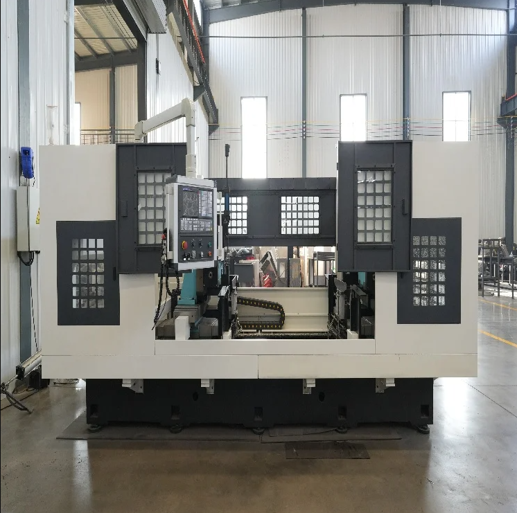
The Bed Angle Sets the Load Path
An automatic slant bed lathe is often described by its angle, but the structure starts with how cutting force travels into the floor. A 45 or 60 degree bed puts the guideways on an inclined plane, so the turret and workpiece sit closer to the machine's center of mass. Under a heavy roughing pass, the bed sees combined bending and torsion, and a one-piece cast or welded base distributes that load better than a bolted frame with shims. The angle also shortens the chip path. That sounds simple until a deep groove turns stringy chips into a bird's nest around the lower turret. Rib placement matters as much as wall thickness. A thick wall with poor rib layout can ring during interrupted cuts, while a well-ribbed base keeps vibration from reaching the spindle nose.
Twin Spindles Need More Than Symmetry
Two spindles on one slant bed look symmetrical, yet symmetry is not the goal. The structure has to hold a shared datum while both heads cut, or the second op inherits the first op's deflection. Spindle boxes are usually mounted on separate pads machined in one setup, and the headstock alignment is checked cold and warm. Synchronization matters when a shaft is turned on both ends at once. A few microns of phase error shows up as a step in the middle of the part. Hydraulic clamping and a rigid tailstock can hide some of that error, but not all of it. Fixture repeatability is the other half. A twin-head layout with excellent spindles and a weak jaw change system will still drift after lunch.
Guideways and Drives Under High-Speed Cuts
High-speed machining is not one number on a spindle nameplate. The structure has to support rapid acceleration without pitching the turret. Linear guideways with preloaded blocks are common on automatic slant bed lathe designs because they reduce stick-slip and make fine interpolation more predictable. Hardened box ways still have a place in heavy interrupted cuts, where damping matters more than speed. The choice should follow the part family, not a brochure. Ballscrew diameter, bearing support, and servo tuning decide whether a fast move ends with a clean stop or a small oscillation. A machine that is fast in a demo can feel nervous in a real cut if the drive train is undersized. Thermal growth in the ballscrew is another factor, and pre-tensioning or a feedback scale can change the result.
Chip Flow, Coolant, and Thermal Balance
The slant is a chip management feature, not just a stiffness feature. Chips fall away from the cutting zone when the angle, coolant pressure, and baffles work together. On a double-head machine, two turrets produce two chip streams, so the base needs separate slopes or a split conveyor. Coolant that pools near the spindle foot can warm the headstock unevenly. A 4-hour test run with a thermal probe on the spindle nose and ballscrew nut is more useful than a short warm-up check. ISO 230-2:2014 gives a consistent way to test positioning accuracy and repeatability, and it is worth asking for results on the actual machine, not a sister unit. The structure should also allow access to the coolant tank and chip conveyor without pulling the turret apart.
A Roller-Shaft Plant Rebuild Case
During a 2021 rebuild at a roller-shaft plant in Jiangsu, a flat-bed pair was replaced with a twin-head slant-bed unit. The first week ran well until a roughing operation on a long sleeve started pushing chips under the lower turret. The fix was not a new machine. A bolt-on baffle and a 15 degree change in nozzle angle cleared the nesting. The more interesting finding was thermal. The shared base stayed stable, but the ballscrew on the upper head grew enough over a long run to shift a finish pass. Adding a warm-up cycle and a mid-shift check brought the spread back in line. The case shows why structure and process have to be commissioned together. A rigid base cannot compensate for a process that ignores heat.
What to Verify Before Signing Off
Before a purchase order, ask for a cut test on a part that represents the hardest combination of hardness, wall thickness, and tolerance. Check the following items with a dial indicator and a test bar, not just a sales sheet:
Spindle nose runout and centerline alignment between heads.
Turret repeatability after 200 tool changes.
Ballscrew backlash and thermal growth after a 4-hour run.
Chip evacuation at the lower turret and at the conveyor discharge.
Access to coolant tank, way lube, and proximity switches.
The table below shows how structural choices map to high-speed behavior. It is a shop-floor comparison, not a specification.
| Structural element | What it changes at speed | Common weak point |
|---|---|---|
| One-piece slant base | Load path and damping | Rib layout, not wall thickness alone |
| Linear guideways | Stick-slip and interpolation | Contamination from fine chips |
| Box ways | Damping in interrupted cuts | Slower rapid moves and more lube |
| Twin spindle alignment | Shared datum between ops | Thermal drift after long runs |
| Ballscrew support | Stop stability and reversal error | Undersized bearing housing |
| Split chip conveyor | Two turret chip streams | Coolant pooling near spindle foot |
For a dual-spindle platform that covers roller shafts, pipes, sleeves, and similar parts, Hengxing's product line of fully automatic double-head CNC lathes, double-head drilling machines, and double-sided milling machines is built around this structural logic. The self-developed line and supply-chain support are worth a look when fixture iteration and spare-parts response are part of the decision.